banner
  • What is CNC Turning?
    What is CNC Turning? Jun 20, 2025
    CNC turning is one of those processes that quietly powers much of the world around us. If you’ve ever handled a metal shaft, a threaded connector, or even a machined knob, chances are it came off a CNC turning machine. It’s a precise, reliable method for shaping round or cylindrical parts, and it’s a staple in industries that can’t afford guesswork, like aerospace, automotive, and medical tech.   But CNC turning isn’t just about spinning metal and shaving off chips. it’s about hitting exact measurements, maintaining consistency across hundreds of units, and keeping production smooth from start to finish. In this blog, we’re breaking down what CNC turning actually is, the types of operations involved, the materials it works best with, and why manufacturers rely on it for mission-critical components. What is CNC Turning?   
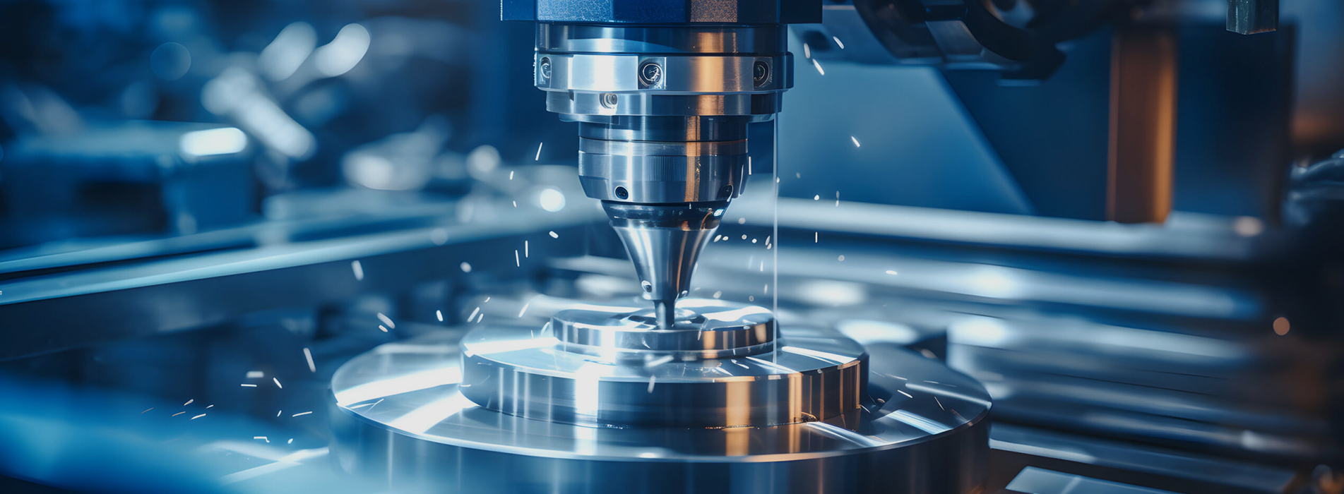
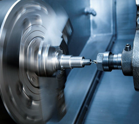
CNC turning is a subtractive machining process that uses computer-controlled lathes to shape material, usually metal or plastic, into precise, cylindrical parts. In simple terms: a piece of raw material spins at high speed while a fixed cutting tool trims it down to size. That’s the core of the CNC turning process.   What sets it apart from other machining methods is the way the material rotates while the cutting tool stays still. That makes it perfect for producing symmetrical shapes like rods, shafts, bushings, and threads. Unlike milling, where the tool moves around the part, CNC turning machining revolves around a central axis. Literally.   
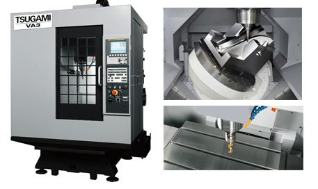
These machines are incredibly accurate, especially when you're dealing with precision CNC turning. You feed in the CAD file, the machine does the rest, and the final product looks exactly like it’s supposed to. If you need hundreds (or thousands) of identical parts, a good CNC turning machine is your best friend.   Curious how turning stacks up against other methods? Check out our breakdown of CNC milling vs CNC turning: which is better? to see which process fits your next project best.   Types of CNC Turning Operations   CNC turning isn't a one-size-fits-all setup. Within the process, there are several specialized operations depending on the design and function of the part you're making. Here's a quick rundown of the most common turn CNC operations:   ● Straight Turning – This is the most basic operation, where the tool moves parallel to the axis of rotation to gradually reduce the diameter of the raw material. For example, if you're machining a steel rod down from 25mm to 20mm for a hydraulic piston, this is the move that does it. ● Taper Turning – Here, the cutting tool moves at an angle to the workpiece axis to create a cone-like shape. You’ll often see this in components like lathe tailstock centers or machine handles where the diameter needs to gradually change. ● Grooving – This involves cutting narrow recesses or slots into the material. These grooves can serve practical purposes like allowing snap rings to fit into place, or controlling the way a part assembles with others. ● Facing – In this operation, the tool moves across the end of the rotating workpiece to create a clean, flat surface. It’s typically the final step when prepping a part’s end, like squaring off the face of a brass gear. ● Threading – Used to carve screw-like features on the inside or outside of a part, threading is common in bolts, pipe fittings, and connector housings. CNC lathes can create threads with high precision that meet standard specs like UNC, UNF, or metric formats.   Now, if you're digging into programming these moves, you'll come across G41 and G42 in CNC turning. These are tool compensation codes. G41 shifts the tool to the left of the path (for left-hand compensation), while G42 moves it to the right. Using them correctly ensures your tool doesn't chew too much off, or not enough. It’s the kind of detail that separates a clean part from a scrapped one. Materials Used in CNC Turning   One of the biggest strengths of CNC turning is how versatile it is when it comes to materials. Whether you're working with metals or plastics, a well-set-up CNC turning machine can handle the job with ease.   
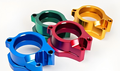
On the metal side, CNC turning parts are often made from:   ● Aluminum – Lightweight, easy to machine, great for aerospace and automotive. ● Stainless Steel – Strong, corrosion-resistant, ideal for medical or food-grade components. ● Brass – Smooth to cut and perfect for fittings and decorative parts. ● Titanium – Known for its excellent strength-to-weight ratio and corrosion resistance. For plastics, common picks include: ● Nylon – Strong and flexible. ● PTFE (Teflon) – Heat- and chemical-resistant. ● ABS – Affordable and easy to work with.   Material choice depends on more than just looks or cost. If you're aiming for precision CNC turning, things like heat tolerance, rigidity, and surface finish all play a role. The right match between material and machine setup is what gives you consistent, high-quality results, every time.   Advantages of CNC Turning   Let’s talk benefits. What makes CNC turning such a go-to across manufacturing? Simple: it delivers quality, speed, and consistency that manual methods just can’t match.   ● Accuracy you can trust: With the right setup, tolerances within a few microns are standard. That level of accuracy is exactly why precision CNC turning is trusted for aerospace components, surgical tools, and other parts where failure isn’t an option. ● Speed and efficiency: Once your program is set, production runs can move fast, especially when using bar feeders and multi-spindle CNC turning machines. ● Repeatability: Whether you’re making 10 or 10,000 parts, they’ll come out exactly the same. ● Cost-effectiveness: High setup costs are offset by low per-part prices in medium to high volumes. ● Design flexibility: Complex shapes, threads, and features that would be tricky or impossible manually are easily achievable with the CNC turning process.   So if your parts need to perform without fail, and you don’t have time for trial and error, CNC turning isn’t just the right option, it’s the only one that makes sense. Applications & Industries   CNC turning shows up in more places than most people realize. It's not just for big factories or industrial plants, CNC turning parts are found in everyday products and specialized equipment alike.   A few industries that rely heavily on CNC turning machining:   ● Automotive – For gears, shafts, and bushings that need to survive wear and torque. ● Aerospace – Where precision isn’t optional. Turned parts like couplings and nozzles need to be flawless. ● Medical – Surgical tools, implants, and housings all benefit from tight tolerances and smooth finishes. ● Electronics – Connectors and enclosures, especially those made from non-ferrous metals, often start with CNC turning services.   Choosing CNC Turning Services   Not all CNC shops are created equal. If you’re looking to outsource or scale up production, choosing the right CNC turning service provider matters more than most people think.   Here’s what to look for:   ● Experience with your material – Turning titanium isn’t the same as working with ABS. The shop should know the difference. ● Precision and inspection standards – Don’t just look at the parts, ask how they’re measured. A reliable CNC shop should have solid quality control practices like in-process gauging, surface finish checks, and documented tolerance reports. ● Equipment and capabilities – Do they use modern, multi-axis CNC turning machines? Can they handle the complexity of your parts? ● Turnaround and flexibility – Deadlines matter. So does the ability to tweak a design mid-run. Also, if you're working with complex geometries, make sure the shop understands things like tool compensation. (Yep, G41 and G42 in CNC turning again. If they don't know how to use those properly, walk away.) At the end of the day, a good CNC partner like doesn’t just deliver parts, they save you time, hassle, and money.   Conclusion   CNC turning does one thing really well: it makes precise, consistent parts without wasting time. Whether you're working with metal, plastic, or something in between, it's one of the most efficient ways to get the job done right.   If you need reliable, no-nonsense CNC machining services, we’re here to help. We work with real tolerances, real materials, and real deadlines, nothing over-promised, just parts that fit and function.   Get in touch with US if you’re ready to take your CNC work seriously.                        
  • CNC Machined Parts
    CNC Machined Parts Jun 27, 2025
    CNC machining technology has become a core tool in modern manufacturing, used in everything from prototyping to mass production. Whether you're a mechanical engineer, designer or manufacturer, a well-designed and optimised part can significantly increase productivity, reduce machining costs and improve part quality. However, every detail in the design can affect the final machining result. In this article, we will share 10 design optimisation tips to help you get a more perfect part in CNC machining. I. Introduction: the need for CNC design optimisation CNC machining not only stands for precision manufacturing, it ensures high precision production, but it relies on upfront design optimisation. The goal of design optimisation is to make the part cleaner and more efficient during machining while ensuring that the part meets the expected performance standards. Design optimisation is not only about machining efficiency, it also has a direct impact on the quality, cost and maintenance of the part. Therefore, designers should pay attention to every detail of CNC machining and fully optimise the design from the early stages.     II. Overview of design optimisation recommendations 1. Understand the basic limitations and possibilities of CNC machining Designers should understand the basic principles and technical limitations of CNC machining so that they can avoid designing overly complex or impractical shapes. Some complex geometries may require more time and cost to machine. Understand the limitations of the machine tool to ensure that the design meets realistic machining capabilities and to avoid wasting resources.   2. Selecting the right material Material is a critical factor in CNC machining. Different materials have different machining characteristics, so designers should choose the right material according to the functional requirements, mechanical properties and budget of the part. Suitable materials not only improve machining efficiency, but also ensure the strength and durability of the parts.     III. Design Optimisation Suggestions 1. Simplify part geometry Reduce unnecessary details and complex surfaces The design should try to simplify the geometry as much as possible, avoiding unnecessary complex surfaces and details. This will make the machining path simpler and reduce tool changes, thus improving machining efficiency and quality.   Optimise hole positions and transition curves In order to improve machining efficiency, the design should try to avoid complex transition curves, which can be replaced by arc transitions instead of straight line connections, making the machining path smoother.     2. Consider the amount of material removal in advance At the design stage, consider the amount of material removal during machining to avoid excessive material removal. Reasonable control of the cutting volume can not only shorten the machining time, but also reduce deformation and unnecessary tool wear.     3. Reasonable selection of tolerances and fits Tolerance selection is crucial in CNC machining. The designer should determine the tolerance according to the functional requirements of the part, and the tolerance requirements can be appropriately relaxed for non-critical functional parts. Overly tight tolerances will increase machining difficulty and cost.     4. Use standardised parts The use of standardised parts can greatly reduce processing time and complexity, reduce manufacturing costs, and improve the interchangeability of parts. For example, using standard bores and threaded holes avoids the complexity and uncertainty of custom machining.     5. Ensure good support and clamping practices Consider how the part is supported and clamped during design to avoid displacement and vibration during machining. Good support design can improve machining accuracy and avoid part deformation.     6. Appropriate chamfer and fillet design Sharp corners will increase the burden on the tool and easily cause tool wear during machining. Appropriate chamfer and fillet design can not only improve the strength and fatigue resistance of parts, but also improve machining efficiency and reduce tool wear.     7. Use reasonable cutting path design The design should take into account the cutting path of the tool and avoid overly complex paths. Optimised paths can reduce machining time, increase productivity and reduce tool wear.     8. Consider subsequent machining processes Considering the subsequent surface treatment process (such as polishing, painting, etc.) can avoid defects in the part design that may affect the surface quality and ensure the efficiency of surface treatment.     9. Optimising design using additive manufacturing In some designs, combining additive manufacturing (e.g. 3D printing) with CNC machining technology can enable the production of some complex structures and reduce material waste, thus optimising the design.     10. Considering efficiency optimisation in mass production During the design phase, the needs of mass production should be taken into account, with a focus on increasing the repeatability of the design to ensure that the machining process is efficient and cost-effective. Proper material selection, optimisation of cutting paths and evaluation of the potential for production automation can significantly increase the efficiency of series production.     IV. the impact of design optimisation on CNC machining Improvement of machining accuracy Reasonable design optimisation can reduce errors and deformations, ensuring high accuracy and consistency in the machining process.   Reduce production costs Optimised design can reduce unnecessary machining steps, reduce tool wear, reduce material waste, thus effectively reducing production costs.   Improve product quality and functionality Design optimisation not only improves machining efficiency, but also ensures the high quality and functionality of the product, so that the final part can better meet customer needs.     V. How to choose the right CNC machining service provider Technical ability and equipment level When choosing a CNC machining service provider, you should consider its technical capability and equipment level. Ensure that the service provider can carry out efficient machining based on design optimisation and deliver high quality products.   Balance of price and delivery time The service provider should offer reasonable prices and flexible lead times to meet the needs of mass production or urgent orders.   Customer Support and Communication Quality CNC machining service providers can provide professional technical support and good customer communication channels to help customers solve problems encountered in the design and production process.     VI. About Keso Kesois a leading CNC machining service provider, we provide comprehensive CNC machining part solutions, from design optimisation to precision machining, each part is manufactured in strict accordance with customer requirements.   Comprehensive CNC Machining Services Keso is able to provide tailor-made design optimisation and CNC machining services for all types of projects, helping customers to achieve efficient production and meet high precision requirements.   Advanced Technology and Equipment We have industry-leading CNC machining equipment that can handle a wide range of complex designs and ensure an efficient, high-quality machining process.   Fast Response and Flexible Delivery Keso is able to respond quickly to customer needs and provide flexible delivery schedules to ensure on-time delivery of parts that meet quality standards.     VII. Conclusion CNC design optimisation is a key component in ensuring efficient production and high quality parts. Through reasonable design optimisation, not only can machining accuracy be improved, but also production costs can be reduced and product functionality and reliability can be enhanced. As technology continues to advance, CNC design optimisation will play an even more important role in the future of manufacturing, helping manufacturers to improve their competitiveness and satisfy their customers' needs.
  • CNC Machining for Metal Project
    CNC Machining for Metal Project Jul 02, 2025
    You’ve got a metal project on your hands, maybe a few prototypes, maybe a production run, and you're wondering if it’s time to upgrade your toolkit. CNC machines aren’t just fancy toys for industrial giants anymore. Today, shops of all sizes rely on them to cut, mill, drill, and shape metal with unshakable accuracy.   But when is the right time to make that leap?   This isn’t just about having cool equipment. It’s about knowing when manual methods, traditional tools, or even outsourcing just aren't cutting it anymore, literally and figuratively. In this guide, we’ll break down five unmistakable signs that a CNC machine for metal is exactly what your shop or project needs.   If you’re working with metal, whether it’s steel, aluminum, or titanium, and you're still relying on manual methods or general-purpose tools, it might be time to rethink your approach.   CNC (Computer Numerical Control) machines offer unmatched precision, repeatability, and efficiency, and they’ve become essential in modern metal fabrication. But how would you know if you really need to buy one?   Let’s look at five clear signs that signal it’s time to invest in CNC technology, or better yet, start working with a professional CNC machining service like ours that already has the machines, expertise, and workflow ready to go.   1. You’re Working with Tough Metals Like Steel or Titanium   If your project involves mild steel, stainless steel, titanium, or other hard alloys, conventional machines often fall short. These materials demand rigid setups, precise feeds, and controlled speeds, the kind of consistency only a CNC machine can provide.   CNC machines for steel are designed to handle the cutting forces and heat that traditional tools can't cope with. They maintain dimensional accuracy over long production cycles, ensuring consistent results across every part.   Trying to cut high-strength materials without the right setup leads to rapid tool wear, warped parts, and wasted material. If that sounds familiar, that’s your first sign.   2. You Require High Precision and Repeatability   Tight tolerances aren't a luxury, they’re often a requirement. If your parts need ±0.01 mm accuracy or better, there’s no room for guesswork.   A CNC machine for metal eliminates manual variability, delivering consistent results from the first part to the last. Whether you’re producing jigs, brackets, enclosures, or mechanical assemblies, CNC machining ensures everything fits as intended, especially when mating parts or interlocking components are involved.   And if you're producing in volume, repeatability is the name of the game.   Curious which CNC machine is right for your metal project? Check out our in-depth guide on choosing the best CNC machines for metal fabrication.   3. Your Production Volume Is Growing Fast   You might have started with one-off prototypes. But if you’re now taking on larger orders or batch runs, scaling up without automation becomes a bottleneck.   CNC machines for metal fabrication don’t get tired, don’t make inconsistent cuts, and can run for hours unattended. For growing shops, that means predictable lead times and the ability to deliver quality at scale, without hiring extra hands or running into fatigue-based errors.   Whether it’s 10 or 1,000 parts, CNC technology gives you production flexibility while keeping waste and labor low.   4. Outsourcing Is Burning a Hole in Your Budget   Let’s be honest: sending parts out for machining gets expensive fast. Between quoting delays, shipping time, and the markup, you’re often paying more than you should.   If you're constantly outsourcing parts and spending thousands per month, it might be time to ask: Is a CNC machine worth it? The short answer? Yes, if your volume and complexity justify it.   But here’s the thing. You don’t need to go all-in and buy your own machine. That’s where JLCCNC’s CNC machining services come in.   We’ve already made the investment, in hardware, tooling, skilled operators, and QA processes, so you don’t have to. You get the benefits of CNC machining without the maintenance, setup, or training overhead. And we work with all common metals, from aluminum and steel to copper and alloys. 5. Your Projects Are Falling Behind Schedule   Time is money, especially in metal fabrication. Manual processes eat up time with setup, rework, and finishing. CNC machines automate those steps and streamline workflows.   Need same-day part fabrication? Done. Need to adjust toolpaths for a new material on the fly? No problem. CNC systems are built for speed and responsiveness.   If you're constantly missing delivery deadlines or waiting days for outsourced parts, it's time to bring your production closer to home. either with your own metal CNC machine or through a partner like us who can deliver fast, high-precision parts.   Is It Time to Embrace CNC?   If even one of these signs hit close to home, your project could benefit from CNC machining, whether that means buying your own machine or working with a professional partner.   And if you’re not ready to commit to buying a CNC bender machine or mill outright, that’s totally fine. That’s where outsourced CNC services like ours bridge the gap, fast turnarounds, tight tolerances, and zero headaches on your end.   Keso offers complete CNC services for metals of all types, with expert machinists, real-time feedback, and production capabilities that scale with you. No matter if you're prototyping or running production batches, we make sure your parts come out flawless, without you ever needing to lift a wrench.   Ready to see how CNC can transform your project?  
  • CNC Machines Work with Different Metals: Steel, Aluminum, Copper Etc. Jul 11, 2025
    CNC machining metal parts may seem straightforward, until you hit chatter, tool wear, or melting edges. Whether it’s stainless steel’s strength or copper’s thermal conductivity, each metal reacts differently to CNC machining. That’s why understanding how CNC machines work with various materials isn’t just helpful, it’s essential.   In this guide, we’ll break down how modern CNC machines cut through popular metals like steel, aluminum, copper, and more. You’ll learn the techniques, challenges, and machine settings that make a difference, plus when it’s best to outsource your metal machining to pros who specialize in getting it right the first time. Can CNC Machines Cut Metal?   Absolutely. CNC machines are designed to cut metals with high accuracy and repeatability. Whether it's a CNC mill, lathe, or plasma cutter, the ability to machine metals depends on the tool type, material hardness, and machine rigidity.   Can a CNC machine cut metal? Yes, but not all machines are equal. Lighter-duty hobbyist machines may struggle with harder metals, while industrial-grade CNCs are purpose-built to handle everything from soft aluminum to hardened steel.   Key considerations when cutting metals: ● Tooling: Carbide tools with coatings like TiN or AlTiN help resist heat and wear. ● Speed & Feed: Slower RPMs and feed rates are necessary for tougher metals. ● Coolant: Essential for heat dissipation and tool longevity.   Looking for reliable CNC machining for any type of metal? Get a quote from our expert machinists, we know how to handle your steel, copper, or aluminum parts without compromise.   CNC Machining Steel: Strength Meets Strategy   Can you CNC machine steel? Absolutely. In fact, it’s one of the most commonly machined materials in manufacturing. However, steel’s toughness demands more from your setup.   CNC Machine for Steel Must Have: ● High spindle torque and rigidity ● Proper clamping to reduce vibration ● Flood coolant to manage heat buildup   Stainless Steel Challenges: ● Tendency to work-harden ● Rapid tool wear ● Requires sharp tools and optimized speeds   For more insights into CNC tolerances and capabilities, check out our blog: How Precise Is CNC Machining Compared to Other Manufacturing Methods?   Machining Aluminum: Speed and Precision   Aluminum is a CNC favorite thanks to its excellent machinability. It's lightweight, dissipates heat well, and allows for high-speed machining with minimal tool wear.   Best Practices: ● Use high RPMs to take advantage of softness ● Chip evacuation is crucial to prevent re-cutting ● Consider aluminum-specific end mills to reduce clogging   Alloys like 6061 and 7075 are widely used in aerospace, automotive, and consumer products.   Copper and Brass: Soft Metals, Sharp Challenges   Copper is thermally and electrically conductive, which makes it ideal for electronics, but a challenge for CNC machining. It tends to gum up tools and generate heat quickly.   Machining Copper: ● Use sharp, uncoated tools ● Apply consistent coolant ● Lower speeds to avoid overheating Brass, by contrast, is much easier to machine: ● Self-lubricating nature reduces friction ● Minimal burr formation ● Ideal for fittings, decorative items, and low-load mechanical parts   CNC Metal Cutter Machines: Do They Differ by Material?   Yes, a CNC metal cutter machine that handles stainless steel will differ in setup compared to one optimized for aluminum. Factors that vary: ● Spindle torque vs speed ● Toolpath strategy (roughing vs finishing) ● Fixture rigidity   CNC machine metal cutting efficiency relies heavily on pairing the right machine and tooling with the specific metal.   Matching Metals to Machining Techniques   Not all CNC machines are suited for every metal: ● Steel: CNC mills or lathes with high torque and flood coolant ● Aluminum: High-speed CNC mills or routers ● Copper/Brass: Standard CNC mills with moderate RPMs and lubrication Metal Tool Wear Machining Speed Finish Quality Machinability Score Steel High Moderate Good 5/10 Aluminum Low High Excellent 9/10 Copper Medium Low Fair 4/10 Brass Low Moderate Very Good 8/10 Why It Pays to Use Experts for CNC Metal Machining   Every metal has its quirks. From edge chipping on aluminum to tool burnout on stainless, one wrong move can ruin an entire job. That’s why it’s smart to trust experienced CNC professionals who know how to optimize settings, select the right tools, and deliver precise results.   Conclusion   CNC machining metals isn’t just about having the right machine, it’s about knowing how to work with the strengths and limits of each metal type. Whether it’s steel’s durability, aluminum’s speed, or copper’s conductivity, every material has its own best practices.   For high-precision parts that demand quality and consistency, partner with a CNC service that brings deep expertise and the right tools to the table.  
  • Robotic CNC Machining Jul 16, 2025
    Robotic CNC machining offers numerous benefits over traditional manufacturing methods, improving productivity and precision. Robotic CNC machining represents a significant advancement in manufacturing technology, merging the precision and efficiency of CNC machining with the versatility and adaptability of robotics. This innovative integration is transforming various industries by improving productivity, ensuring consistent quality and supporting the mass production of complex parts with ease. If you are curious about the topic of robotic CNC machining and wish to learn more about its potential applications, you have come to the right page! In this article, we share the fundamentals of robotic CNC machining and explore the role of robotics in manufacturing. We will also look at the various advantages and applications of robotic CNC machining, to gain a comprehensive insight into its present capabilities and future potential. But before we dive in, let's understand what robotic CNC machining is and how it works. What is Robotic CNC Machining? Robotic CNC machining integrates robotics with CNC technology to enhance manufacturing capabilities. This combination leverages the strengths of both technologies, resulting in a more efficient and versatile production process. It involves the use of robotic systems to assist or perform CNC machining tasks. This can range from simple tasks like loading and unloading parts to more complex operations where robots perform the actual machining. Types of Robotic CNC Machining Setups Robot-Assisted CNC Machining: Robots assist traditional CNC machines by handling tasks such as part loading, unloading, and repositioning. This setup improves efficiency and reduces human involvement in repetitive tasks. Fully Integrated Robotic CNC Machining Cells: In these setups, robots and CNC machines are fully integrated into a single system. Robots perform the machining tasks directly, offering greater flexibility and capability to handle complex geometries and operations. Key Components and Technologies Involved Robotic Arms: Equipped with various end effectors such as grippers, cutters, and drills, robotic arms perform precise machining operations. End Effectors: Tools attached to the robotic arms to interact with the workpiece, including milling cutters, drills, and grinding wheels. CNC Machines: Traditional CNC machines modified to integrate with robotic systems, enhancing their capabilities. Control Software: Advanced software systems that coordinate the actions of the robots and CNC machines, ensuring synchronised and efficient operation. Advantages of Robotic CNC Machining Robotic CNC machining offers numerous benefits over traditional manufacturing methods, improving productivity, and precision in various industrial applications. Improved Productivity and Efficiency Continuous Operation: Robotic systems can operate continuously without breaks, significantly increasing overall productivity. This ability to work 24/7 reduces production times and meets high demand more effectively. Reduced Downtime: Automation minimises human error and machine downtime, as robots can quickly adjust to new tasks without requiring extensive reconfiguration or setup. Improved Precision and Quality Reduced Human Error: Robotic systems eliminate the inconsistencies associated with manual labour. They execute tasks with high accuracy and repeatability, ensuring consistent quality across all produced parts. Consistent Performance: Robots maintain precision over long periods, providing uniform results that meet stringent quality standards. Programmable to Handle Varying Degrees of Complexity Handling Complex Geometries: Robotic CNC machining can manage intricate designs and complex geometries that would be challenging or impossible with manual machining. Customisation: Robots can be easily reprogrammed to accommodate changes in product design or manufacturing requirements, allowing for rapid adaptation to new projects and custom orders. Cost-Effectiveness in the Long Run Reduced Labour Costs: Automating machining processes decreases the need for manual labour, lowering operational costs. While the initial investment in robotic systems may be high, the long-term savings in labour expenses are substantial. Increased Throughput: Enhanced efficiency and reduced downtime lead to higher production rates, which translates to better utilisation of resources and faster return on investment. Applications of Robotic CNC Machining Robotic CNC machining finds applications across various industries, driven by the need for precision, efficiency, and the ability to handle complex tasks. Aerospace Industry The aerospace sector requires parts with extremely tight tolerances and high precision. Robotic CNC machining is ideal for manufacturing components such as turbine blades, engine parts, and structural elements, ensuring high-quality standards and consistency. Automotive Manufacturing In the automotive industry, robotic CNC machining is used for producing engine components, transmission parts, and intricate bodywork. The flexibility and precision of robotic systems allow for the efficient production of both standard and customised parts. Medical Device Production The medical field demands high precision and cleanliness in manufacturing. Robotic CNC machining is employed to produce medical implants, surgical instruments, and diagnostic equipment with the accuracy and consistency required to meet regulatory standards. Electronics and Semiconductor Manufacturing In electronics and semiconductor manufacturing, robotic CNC machining is used to create components like circuit boards, connectors, and housings. The precision of robotic systems ensures the integrity of these intricate parts, which are essential for the proper functioning of electronic devices. General Industrial Applications Across various industries, robotic CNC machining is utilised for general manufacturing tasks. From creating moulds and dies to producing consumer goods, the versatility and efficiency of robotic systems enhance overall production capabilities. Technical Considerations and Challenges Integrating robotics with CNC machining presents several technical considerations and challenges that must be addressed to ensure seamless operation and optimal performance. Integration Challenges Synchronising robotic systems with CNC machines can be complex due to differences in their operational protocols and communication interfaces. One of the primary challenges is achieving real-time coordination between the robot and the CNC machine to ensure smooth transitions and precise operations. Solutions such as advanced control software and middleware that facilitate communication between different systems are essential for overcoming these integration hurdles. Software Compatibility The software used to control robotic CNC machining systems must be compatible and capable of handling complex tasks. This involves integrating CAD/CAM software with the robot’s control system and the CNC machine’s operating software. Ensuring compatibility and smooth data flow between these software components is crucial for efficient operation. Additionally, software updates and customisation may be necessary to meet specific application requirements. Maintenance and Reliability Regular maintenance is vital for the longevity and reliability of robotic CNC systems. This includes routine checks, lubrication, calibration, and replacement of worn-out parts. Implementing predictive maintenance strategies, powered by AI and machine learning, can help anticipate potential issues and minimise unexpected downtime. Ensuring a robust maintenance schedule can significantly enhance the reliability and performance of robotic CNC machining systems. Safety Measures and Standards Operating robotic CNC systems involves inherent safety risks due to the interaction between high-speed machinery and robotic arms. Implementing stringent safety protocols and standards is crucial to protect operators and equipment. This includes using safety barriers, emergency stop mechanisms, and ensuring compliance with industry-specific safety standards. Proper training for operators and regular safety audits can further mitigate risks and ensure a safe working environment. Economic and Environmental Impact Robotic CNC machining not only offers technical advantages but also brings significant economic and environmental benefits. Cost Analysis The initial investment in setting up robotic CNC systems can be substantial, including the cost of robots, CNC machines, software, and integration services. However, this investment often leads to significant long-term savings. Automated systems reduce labour costs by minimising the need for manual intervention. In addition to this, increased production efficiency and reduced downtime contribute to a faster return on investment. A detailed cost analysis, considering both upfront expenses and long-term savings, can demonstrate the economic viability of adopting robotic CNC machining. More Sustainable Robotic CNC machining contributes to more sustainable manufacturing practices. The precision of robotic systems reduces material waste by ensuring accurate cutting and shaping, leading to more efficient use of raw materials. Additionally, the ability to operate continuously without breaks optimises energy consumption. Implementing robotic CNC machining can also reduce the carbon footprint of manufacturing operations by minimising the need for additional resources and energy-intensive rework. Customisation and Scalability One of the standout features of robotic CNC machining is its ability to be customised and scaled according to specific industry needs and production volumes. Tailoring Solutions Robotic CNC machining systems can be tailored to meet the unique requirements of different industries. For example, the aerospace industry may require robots with specialised end effectors for handling delicate materials, while the automotive industry might focus on high-speed production capabilities. Customising the robotic setup, including the choice of robots, end effectors, and control software, ensures that the system aligns perfectly with the desired application and production goals. Scalability Robotic CNC machining systems are highly scalable, making them suitable for both small and large-scale operations. For small businesses, a basic setup with a single robot and CNC machine can significantly enhance productivity and precision. As the business grows, additional robots and CNC machines can be integrated into the system, allowing for increased production capacity without overhauling the entire setup. This scalability ensures that robotic CNC machining can adapt to evolving business needs and market demands, providing a flexible and future-proof manufacturing solution. Future Trends and Innovations The future of robotic CNC machining is shaped by ongoing advancements in technology, particularly in the areas of artificial intelligence (AI), machine learning, and connectivity. Advances in AI and Machine Learning AI and machine learning are increasingly being integrated into robotic CNC machining systems. These technologies enable robots to learn from data, optimise processes, and make real-time adjustments to improve precision and efficiency. Predictive maintenance, powered by AI, helps in anticipating and addressing potential issues before they cause downtime. Development of Collaborative Robots (Cobots) Collaborative robots, or cobots, are designed to work alongside human operators. In CNC machining, cobots can assist with tasks that require human dexterity and decision-making, while still offering the precision and efficiency of robotic systems. This collaboration enhances productivity and safety in manufacturing environments. Impact of Industry 4.0 and the Internet of Things (IoT) The integration of Industry 4.0 principles and IoT technologies is transforming robotic CNC machining. Smart factories equipped with interconnected machines and sensors enable real-time data collection and analysis, leading to more efficient and adaptive manufacturing processes. IoT allows for seamless communication between robots and CNC machines, facilitating coordinated operations and enhanced performance. Potential for Further Automation and Integration The trend towards increased automation and integration is set to continue. Future developments may see even more sophisticated robotic CNC machining cells, where robots handle multiple tasks, from raw material handling to finished product inspection. This level of integration will further streamline production processes and reduce the need for human intervention. The future of robotic CNC machining looks promising, with innovations aimed at enhancing efficiency, precision, and flexibility. As technology continues to advance, robotic CNC machining will play a pivotal role in the evolution of manufacturing industries. Final Thoughts As the manufacturing landscape continues to evolve, embracing advanced technologies like robotic CNC machining is crucial for staying competitive and meeting the demands of modern production. At Rotec, we specialise in precision engineering and complex CNC machining, leveraging the latest innovations to deliver unparalleled quality and efficiency. Our expertise in complex CNC machining allows us to tackle even the most intricate projects with precision and reliability. If you are ready to take your manufacturing capabilities to the next level,
  • What is CNC Machining in Manufacturing? Jul 29, 2025
    Computer Numerical Control (CNC) is an automated manufacturing process that controls and operates machinery—such as lathes, mills, drills, and more—by way of a computer. It has evolved the manufacturing industry as we know it, streamlining the production process and allowing complex tasks to be done with precision and efficiency. If you are looking to break into the field of manufacturing, CNC machining offers a cutting-edge career on the frontlines of innovation and technology. If you are looking to learn more about the manufacturing industry, read on. Below, we’ll explore: What is CNC? What is a CNC machine and how does it work? The importance of CNC machining What is a CNC machinist? First, let’s start with the basics of CNC and what it stands for. What is CNC? CNC stands for Computer Numerical Control, which refers to the computerized operation of machining tools used in manufacturing. CNC machines operate using pre-programmed software and codes, which tell each machine the exact movements and tasks to complete. For example, a CNC machine might cut a piece of material (such as metal or plastic) based on instructions from a computer, meeting the specifications pre-coded into the program—all without a manual machine operator. CNC is used to operate a range of complex machinery, such as grinders, lathes, turning mills, lasers, and routers, all of which are used to cut, shape, and create different parts and prototypes. What is a CNC machine and how does it work? A CNC machine is a type of machinery operated by computers and used for the fabrication of different parts and goods. CNC machines might be used to print, cut materials, manipulate parts, create goods from scratch, and more. They eliminate the need for a human operator to control the tools manually, thus improving accuracy and consistency in production. CNC machines work by carrying out pre-programmed sequences of commands from computer software. These advanced machines do not require manual control (e.g. no hand levers or wheels). Rather, they function using CNC machining language – called G-code and M-code – which gives the machines precise measurements for production, like feed rate, speed, location, and coordination. CNC machines have a microcomputer that is stored inside the machine’s control unit (MCU). With each task the machine has to complete (e.g. cutting metal parts), the MCU receives a customized code that tells the machine exactly what to do. This code is developed using blueprints or computer-aided design (CAD) drawings and then loaded onto the machine to begin operations. G-code controls the movement and function of a machine. M-code is used to control the operation’s external movements. These codes can be written manually or generated by CAD and CAM software. Common types of CNC machines include, but are not limited to: CNC Lathes: Used for turning operations CNC Mills: Used for cutting and drilling operations CNC Plasma Cutters: Used for cutting metal using a plasma torch CNC Routers: Used for cutting various materials like wood, plastic, and metal 3D Printers: Additive manufacturing machines that build objects layer by layer While CNC machines are largely automated, machinists are still needed to ensure proper operations and performance. So, once a machine is programmed and coded, a CNC machine operator is needed to step in. This machinist will conduct a test run to ensure everything is working properly before the manufacturing can fully begin. Otherwise, there is a risk of damage to the machine and/or product. The importance of CNC machining In the past, manufacturing facilities were full of heavy (and often dangerous) equipment. The working conditions were not always ideal, and the jobs were quite arduous. While some physical labor is still required in manufacturing, modern manufacturers are now relying on advanced, automated equipment and CNC technology to complete complex tasks. This helps to make working conditions safer, production easier, processes more efficient, and manufacturing as a whole cleaner and more sustainable. CNC, along with computer-aided design (CAD) and computer-aided manufacturing (CAM) software, have put technology at the forefront of manufacturing and changed the industry as we know it. When compared to manual manufacturing, the benefits of Computer Numerical Control include: Better working conditions and improved worker safety Greater precision and consistency across manufacturing, plus reduced risk of human error Less waste, as CNC machines are so precise, accurate, and optimized Reduced costs for production, including lower operating expenses and energy consumption Streamlined and faster production, without bottlenecks, due to automation Tech-driven careers, where workers can secure advanced jobs using cutting-edge technology     What is a CNC machinist? A CNC machinist, also known as a CNC operator, is responsible for running and overseeing CNC machinery. While it’s true most machines are automated, CNC machinists are still needed to set up, test, operate, and maintain the equipment. On a daily basis, CNC machinists can be found: Aligning, securing, and adjusting cutting tools and workpieces into machinery Examining and testing machines for any issues or inefficiencies Measuring and testing completed products for defects Monitoring the feed and speed of CNC machines Reading blueprints, sketches, or computer-aided design (CAD) and computer-aided manufacturing (CAM) files Setting up, operating, and disassembling CNC machines Smoothing the surfaces of parts or products for completion Turning, milling, drilling, shaping, and grinding machine parts to specifications as needed CNC machinists can work in a range of exciting industries, including aerospace, motor vehicle manufacturing, mechanical engineering, metalworking, and more. These professionals must be proficient in technical drawings, mechanical design, CNC operation, mathematics, and computer programming. Therefore, hands-on training is required to succeed in this role. For aspiring CNC machinists, postsecondary training is recommended to gain experience. Professional certification is also suggested (though voluntary) to show employers your dedication and proficiency in the field.
  • Thread Milling vs. Tapping Aug 12, 2025
    Threading a hole sounds simple, until you’re deciding between thread milling and tapping. Both methods are staples in CNC machining and manual operations, but they serve different purposes, machines, and tolerances. Whether you're threading aluminum, stainless steel, or titanium, choosing the wrong method can mean broken tools, scrapped parts, or wasted hours.   Let’s break down the real differences between thread milling vs tapping, when to use one over the other, and how to choose the right tool for your part. What is Tapping?   Tapping is the traditional method of creating internal threads by driving a tap, a hardened cutting tool, into a pre-drilled hole. It’s fast, easy to set up, and widely used in manual and CNC operations.   There are three common types of taps: ● Hand taps – used manually with a T-handle ● Spiral point taps – best for through holes ● Spiral flute taps – best for blind holes   Taps are typically specific to one thread size and pitch, which makes them convenient but rigid in flexibility.   What is Thread Milling?   Thread milling, on the other hand, uses a rotating tool called a thread mill to cut threads with a helical interpolation motion. The tool enters the hole and follows a spiral path to form the thread, using a CNC program to control pitch and depth.   There are three types of thread mills: ● Single-point thread mills – extremely flexible for custom threads ● Multi-form thread mills – cut the full profile in one pass ● Indexable thread mills – ideal for large threads or production runs   Thread milling may require more programming and setup time, but it shines in areas tapping simply can't reach.   Thread Milling vs Tapping: Head-to-Head Comparison   Let’s stack up thread milling vs tapping in the areas that matter most: Thread Milling and Tapping in Different Materials   When working with softer materials like aluminum or mild steel, tapping is fast and rarely problematic.   But when dealing with: ● Stainless steel ● Tool steel ● Superalloys   …thread milling provides better tool life and reduces the risk of tool breakage. This makes it a smart choice for aerospace, medical, and high-precision industries.   CNC Programming Differences   Tapping usually relies on a simple cycle (G84 for right-hand, G74 for left-hand tapping). Easy to program, minimal variables.   Thread milling, on the other hand, requires: ● Circular interpolation (G02/G03) ● Depth control ● Helix angle programming   While this adds complexity, modern CAM software and CNCs make it increasingly easier.   Tool Life and Cost Considerations   Taps wear out quickly in hard materials and can break, especially in blind holes with poor chip evacuation.   Thread mills, although more expensive upfront, last longer and are more forgiving, especially if you’re threading near the bottom of a hole. Plus, if a thread mill breaks, you typically don’t lose the entire part.   Is Thread Milling Better Than Tapping?   It depends on your application.   Tapping wins when: ● You're working in high-volume production ● Thread size and material are standard ● Speed and cost-per-hole are critical   Thread milling is better when: ● You're threading expensive or difficult materials like Inconel or titanium ● You need flexibility in thread sizes or depths ● You want to avoid breaking taps in blind holes ● You're using CNC machines capable of helical interpolation   So, is thread milling better than tapping? In terms of flexibility and safety, yes. But in terms of speed and simplicity, tapping still holds the crown for everyday work.   At KESO, we specialize in precise, reliable threaded parts, no matter the size, material, or threading method. Whether you need help programming a thread milling cycle or want bulk tapping production, we’re here to help.   Upload your design file and get a free quote here, we’ll recommend the best process for your job.   Final Word: Which One Should You Use?   Use tapping when: ● You need speed and low cost ● You’re working on large batches with consistent threads ● You have limited CNC capabilities   Use thread milling when: ● You're working with tough or expensive materials ● Flexibility, precision, and thread quality matter ● You're threading blind holes or varying thread diameters   Pro tip: If you’re threading critical parts, test both methods. A single broken tap can cost more than investing in a thread mill.                                  
  • End Milling vs Face Milling Aug 12, 2025
    In the world of CNC machining, milling is a go-to process, but not all milling operations are the same. End milling and face milling are two widely used machining methods, each optimized with distinct tooling designs, cutting geometries, and suited for different types of operations. While they both shape metal through rotary cutters, they differ in how, where, and what they cut.   In this blog, we’ll break down the differences between end mills and face mills, compare performance, and help you decide which one to use for your next project. Whether you're a machinist, engineer, or sourcing precision CNC services, this guide gives you the clarity you need. What is End Milling?   End milling is a type of machining operation where the cutting tool enters the material perpendicularly, using the sides and the end of the cutter to remove material. The tool is usually an end mill, which can plunge, contour, slot, pocket, and even drill, making it extremely versatile.   What Are End Mills?   End mills resemble drill bits but differ significantly, they feature flutes along the sides and tip, enabling them to cut not just vertically, but also horizontally and laterally across the X, Y, and Z axes. They’re used in vertical milling machines and CNC routers for operations like: ● Profiling edges ● Pocketing cavities ● Engraving ● Slotting ● Contour finishing   What are end mills used for? Nearly everything that requires precision: custom parts, complex geometries, mold features, prototypes, and even post-casting refinement.   Types of End Mills   End mills come in various types, each engineered to suit particular materials and machining needs. For instance: ● Square End Mills: These have flat ends and are commonly used for creating clean edges, flat-bottomed slots, and pocketing operations. ● Ball Nose End Mills: For 3D contoured surfaces. ● Corner Radius End Mills: These have rounded edges at the tip, offering greater durability and reducing tool wear, especially during high-stress cuts. ● Roughing End Mills: Designed with serrated or knurled flutes, these tools aggressively remove large volumes of material quickly during the initial roughing phase.   If you're working with non-ferrous metals, such as aluminum, you'll want end mills for aluminum, typically featuring polished flutes, high rake angles, and fewer flutes (2-3) to evacuate chips efficiently.   What is Face Milling?   Face milling is the process of cutting with the face, or bottom, of the tool rather than the sides. It’s mainly used to produce flat surfaces (faces) on large workpieces or to remove material quickly.   The tool used is called a face mill, and it typically features multiple indexable inserts set on a large-diameter body. It’s mounted horizontally and makes shallow passes across the surface.   When Should You Use Face Milling?   Face milling is ideal for: ● Creating perfectly flat surfaces ● Squaring off blocks of metal ● Removing large amounts of material ● Prepping stock for further machining   End Milling vs Face Milling: Key Differences   Let’s get into the real comparison, what sets them apart beyond just tool geometry? If you’re producing a custom bracket with pocketed holes, end milling is your tool. But if you’re machining a flat steel plate to prep it for further ops, go for a face mill.   For parts with deep cavities, steep angles, or complex 3D profiles, 5 axis CNC machining can unlock new possibilities by allowing end mills to approach the workpiece from multiple directions, learn more about how it works here.   Tooling Considerations: End Mill vs Face Mill   When choosing between an end mill vs face mill, the decision often comes down to tool size, machine horsepower, and part geometry.   ● Face mills are generally large-diameter tools. They need a more rigid spindle and plenty of torque. ● End mills, especially small-diameter ones, are more flexible and precise, ideal for smaller machines or intricate jobs.   Tip: For tight internal corners or 3D shapes, you’ll need an end mill. Face mills can’t handle intricate geometries.   Material Compatibility   Both tools can work with a wide range of materials, steel, aluminum, copper, stainless, and titanium, but the cutter geometry matters.   ● For aluminum, use high-helix, polished end mills and face mills with aggressive rake angles. ● For steel, choose coated carbide tools and optimized chip breakers. ● For stainless steel, tool rigidity and coolant flow are critical to avoid work hardening.   Need your parts precision-machined without the hassle of choosing tooling? Our CNC milling services deliver high-tolerance results using the right tools, so you get the perfect part every time. Request a quote now.   Cost and Efficiency   From a production cost perspective: ● Face milling is more efficient for stock removal. The high material removal rate makes it ideal for bulk surfacing. ● End milling can be slower but delivers high accuracy, lower finishing costs, and fewer tool changes for detailed work. Want to reduce cycle times in batch production? Use face mills to prep the block, then end mills to add precision features.   Tool Wear and Life   Tool longevity depends heavily on the application: ● End mills wear down faster in hard materials and corners. ● Face mills offer longer life due to indexable inserts, just replace the insert, not the whole tool.   Both benefit from the right feed rates, spindle speeds, and coolant strategy.   Curious how end mill selection affects performance? Read our full guide on End Milling and make smarter tooling decisions.   Which One Should You Choose?   Ultimately, the decision between end milling vs face milling comes down to your project’s goals: ● Want flatness and speed? Choose face milling. ● Need geometry and accuracy? Go for end milling.   In many cases, both are used together: face mill to square the block, end mill to finish the features. Understanding the role of each helps optimize your machining strategy, reduce cycle times, and extend tool life.              
  • From CAD to CNC: A Complete Guide to Transforming Digital Designs into Machined Parts Aug 21, 2025
    The journey from a concept in an engineer's mind to a physical part in your hand is a fascinating feat of modern manufacturing. At the heart of this process lies a critical transition: converting a digital CAD model into instructions a CNC machine can understand and execute. This seamless flow from design to reality is what enables the precision and complexity of modern machined components.   This article breaks down the essential steps, software, and considerations involved in transforming a CAD file into a finished CNC machined part. The digital thread: From CAD design to CAM programming to physical part via CNC machining.   Step 1: The Foundation - Creating the CAD Model   It all starts with Computer-Aided Design (CAD). Software like SolidWorks, Autodesk Fusion 360, AutoCAD, Siemens NX, or Creo Parametric is used to create a detailed 2D or 3D model of the part.   · What it is: A digital blueprint containing all the geometric data—dimensions, tolerances, threads, and features—of the desired part. · Key Output: The final design is exported in a neutral file format that can be read by various other software. The most common format for this transition is STEP (.step or .stp) or IGES (.iges), as they preserve solid geometry information. Native format files (e.g., .SLDPRT for SolidWorks) are also used when staying within the same software ecosystem.   Design for Manufacturability (DFM) is crucial at this stage. A designer must consider the capabilities and limitations of CNC machining:   · Tool Access: Can a cutting tool physically reach all features? · Internal Sharp Corners: Most cutting tools are cylindrical, making perfect internal sharp corners impossible; a radius is always needed. · Wall Thickness: Very thin walls can be difficult to machine without vibration or breaking. · Material Selection: The choice of material (aluminum, steel, plastic, etc.) will directly impact machining strategies, tool selection, and cost.   Step 2: The Bridge - Translating with CAM Software   The CAD model defines the what—the final shape. The Computer-Aided Manufacturing (CAM) software defines the how—the machining process.   · What it is: CAM software (often a module within CAD software like Fusion 360 or a standalone program like Mastercam) imports the CAD model. The programmer then uses it to create a toolpath—a set of instructions that dictates the tool's movement across the workpiece. · Key Activities in CAM:   1. Setup Orientation: Defining how the raw material (stock) will be held in the machine vise or fixture and which side will be machined first.   2. Tool Selection: Choosing the appropriate cutting tools (end mills, drills, taps, etc.) from a digital library, specifying their diameter, length, and material.   3. Defining Toolpaths: Creating sequences of operations like:      · Roughing: Removing large amounts of material quickly.      · Finishing: Making final passes to achieve the required surface finish and tight tolerances.      · Drilling: Creating holes.      · Contouring: Profiling the outer shape of the part.   4. Setting Parameters: Inputting critical values such as spindle speed (RPM), feed rate (how fast the tool moves), and depth of cut. CAM software generates visual toolpaths that show the precise route the cutting tool will take to create the part.   Step 3: The Machine's Language - Post-Processing to G-Code   The toolpaths generated in CAM are not yet ready for the machine. They are generic. A post-processor acts as a translator.   · What it is: A post-processor is a software plugin (often specific to the brand and model of the CNC machine) that converts the generic toolpath data into a specific G-code file. · What is G-code? G-code is a standardized programming language (using commands like G01 for linear move, M03 to start the spindle) that controls all actions of a CNC machine: movement, speed, feed, coolant on/off, and tool changes. · Why it's needed: Different CNC controllers (e.g., Fanuc, Haas, Heidenhain) have slight variations in their G-code dialect. The post-processor ensures the output file is perfectly tailored for the target machine, avoiding crashes or errors.   The final output of this step is a .NC or .TXT file containing the G-code program.   Step 4: Execution - Running the Program on the CNC Machine   With the G-code program ready, the machinist takes over.   1. Setup: The raw material is securely fastened to the machine bed. The correct tools are loaded into the machine's tool changer or carousel. Each tool is carefully measured to establish its length and diameter offset in the machine's controller. 2. Work Zero Setting: The machinist defines the program's "zero point" (origin) on the workpiece, telling the machine where the part is located in its coordinate system. 3. Verification: Before running the program on the actual material, a dry run or simulation is often performed to check for any errors or potential collisions. 4. Machining: The G-code program is loaded into the machine's controller. The start button is pressed, and the machine executes the instructions autonomously, cutting away material until the part is complete.   Conclusion: A Streamlined Digital Thread   The path from CAD to CNC is a powerful example of integrated digital manufacturing. By understanding each step—from DFM in CAD, to toolpath generation in CAM, to post-processing for G-code, and finally, precise machine execution—engineers and machinists can work together to produce high-quality parts efficiently and accurately. This digital thread not only speeds up prototyping and production but also unlocks the potential for creating incredibly complex geometries that would be impossible to make manually.     Disclaimer: The images used in this article are for illustrative purposes and are placeholders. In a real publication, original or licensed high-resolution images and specific software screenshots would be used.                                                    
  • CNC high-precision low-reflectivity optical components Aug 27, 2025
    The pinnacle of precision manufacturing: CNC high-precision and low-reflectivity surface treatment technology  In the modern precision manufacturing field, the two core indicators of parts - dimensional accuracy and surface performance - often directly determine the quality and reliability of the final product. CNC (Computer Numerical Control) processing technology has long been the cornerstone for achieving micron-level or even nanometer-level dimensional accuracy. However, when the application scope expands to high-precision fields such as optics, aerospace, and semiconductors, another key indicator emerges: low reflectivity of the surface.  Combining high-precision machining with low-reflectivity surface treatment represents one of the highest levels of CNC manufacturing technology today. This is not only a test of the performance of the machine tools, but also a comprehensive challenge to materials science, tool path planning, and post-processing techniques.   I. Why is low reflectivity necessary? Beyond the "aesthetic" functional requirements  Low-reflectivity surfaces are far more than just for eliminating unnecessary reflections (or "anti-glare") to achieve aesthetic effects; behind this lies a profound functional need:  Optical system performance: In optical devices such as cameras, telescopes, microscopes, and laser radars, the reflected light from internal components (such as barrels, supports, and aperture blades) can form stray light, significantly reducing image contrast, causing ghost images, and even increasing signal noise. Low reflectivity surfaces can effectively absorb stray light, improving imaging quality and system signal-to-noise ratio. 2. Military and aerospace stealth: The high reflectivity of equipment surfaces is a significant characteristic of radar waves and infrared detection. Through low reflectivity treatment, it can significantly reduce its radar cross-section (RCS) and infrared characteristics, enhancing stealth performance and survivability.   3. Semiconductor and sensing technology: In the interiors of lithography machines and wafer processing equipment, any unnecessary reflection may interfere with extremely precise optical paths or sensor readings, leading to manufacturing defects. The shells of sensors themselves also require low reflectivity to ensure measurement accuracy.   4. Medical and research equipment: Such as endoscopes, high-precision experimental instruments, etc., they all need to minimize internal light interference to ensure the purity of observation and data.   II. How to Achieve It? The Integration of High-Precision CNC and Low Reflectivity Technology  To achieve a part with both high precision dimensions and low reflectivity is a multi-stage systematic project:  High-precision CNC processing: Foundation  · Ultra-high precision machine: Utilizing linear grating rulers with nanometer-level resolution, thermal compensation systems, highly rigid bed and spindle, and high-end five-axis CNC machines, this ensures the utmost precision in geometric shape and dimensions. · Precise cutting tools and strategies: Employing diamond tools or ultra-fine particle carbide tools, combined with optimized cutting parameters (rotation speed, feed rate, depth of cut) and tool paths (such as slow-tool servo turning), excellent surface quality (low roughness) is achieved at the initial stage of processing, laying a perfect foundation for subsequent low-reflection treatment.  2. Achieving low reflectivity surface treatment technology: The core of low reflectivity essentially involves altering the microscopic structure or chemical composition of the surface to enhance light absorption and reduce specular reflection. The main technical approaches include:  · Surface microstructure processing (texturing): · Technical principle: Utilizing the extremely high positioning accuracy of CNC machines, dense micrometer or nanometer-sized grooves, depressions, or complex three-dimensional structures can be machined on the surface of the parts. These structures can be regarded as "light traps", as light entering them undergoes multiple reflections and absorptions, making it difficult to escape again, thereby achieving the "blackening" effect. · Implementation method: The surface microstructure can be directly shaped through five-axis milling, femtosecond laser ablation, chemical etching, etc. · Special coatings/adsorptions: · Technical principle: On the machined base material, a layer of material with high light absorption properties, such as black chromium, black nickel, carbon nanotube (CNT) coating, or specific ceramic coating, can be covered through physical vapor deposition (PVD), chemical vapor deposition (CVD), or spraying processes. · Advantages: Strong selectivity, capable of designing coatings for different wavelengths (such as visible light, infrared, radar waves), with extremely high absorption efficiency. However, the coating thickness must be strictly controlled to avoid affecting the high precision dimensions of the parts. · Chemical conversion treatment: · Technical principle: Through chemical methods (such as anodic oxidation, black oxidation), a porous and rough chemical conversion film can be generated on the metal surface (especially aluminum, steel). This film itself has light absorption properties. Common examples include black anodic oxidation of aluminum alloys.  · Note: The treatment process needs to be precisely controlled to avoid affecting the precise dimensions.  3. Collaboration and Challenges: The greatest challenge lies in the fact that subsequent low-reflection treatments (such as coating, oxidation) will introduce extremely thin additional layers, which may alter the final size of the part. Therefore, "compensatory design" must be carried out at the initial high-precision CNC processing stage, taking into account factors such as coating thickness in advance, and conducting "negative allowance" processing to ensure that the final size of the processed part still perfectly meets the design requirements.    
  • CNC Surface Machining: Comprehensive Guide to Types, Charts and Tests Sep 05, 2025
      Surface quality is a key indicator for measuring the precision of CNC machined parts. It involves three aspects: roughness (microscopic unevenness), waviness (macroscopic periodic unevenness), and texture (machining tool path direction).   I. Surface Processing Types (How to Achieve)   Different processing operations and strategies can achieve different surface finishes. The following is arranged in order from coarse to fine. Typical achievable roughness (Ra) description of processing types and applicable scenarios Rough machining of 12.5 μm - 3.2 μm uses a large cutting depth and high feed rate to quickly remove the material, leaving obvious tool marks and a poor surface. When the parts are initially formed, machining allowances are reserved for non-critical surfaces. Semi-finishing is 3.2 μm - 1.6 μm to prepare for finishing, remove the marks of rough machining, and ensure an appropriate allowance for finishing. The final processing of most non-mating surfaces, installation surfaces, etc. Conventional finishing of 1.6 μm - 0.8 μm adopts small cutting depth, small feed rate and high rotational speed. The knife marks are visible to the naked eye but smooth to the touch. The most common precision requirements are used for static mating surfaces, sealing surfaces, bearing housings, etc. High-precision finishing of 0.8 μm - 0.4 μm requires optimized parameters, sharp cutting tools, high-rigidity machine tools and effective cooling. The surface is extremely smooth. Dynamic mating surfaces, hydraulic cylinder walls, and high-load bearing surfaces. Superfinishing of 0.4 μm - 0.1 μm requires the use of single crystal diamond tools, extremely high machine tool accuracy and a stable environment (constant temperature). Optical components, precision instrument surfaces, silicon wafer processing. Manual polishing/grinding < 0.1 μm: Remove the knife marks by hand or mechanical means such as sandpaper or oilstone to achieve a mirror-like effect. Appearance parts, mold cavities, surfaces of food and medical equipment. Ii. Symbols, Charts and Annotations (How to Specify)   Engineers clearly specify the requirements on the drawing through surface roughness symbols.   1. Basic symbols   Explanation of symbol meanings √ Basic symbols indicate that the surface can be obtained through any process and are meaningless to use alone. Youdaoplaceholder0 is the most commonly used to remove materials. It indicates that the surface is obtained by removing the material through processing methods such as milling, turning and drilling. "Non-removal of material refers to surfaces formed through casting, forging, rolling, etc., which do not require processing."   2. Complete annotation (taking the removal of material symbols as an example) :   ` ` ` [a] - Roughness parameters and values (such as Ra 0.8) [b] - Processing methods (such as "milling ") [c] - Texture direction symbols (such as "=") [d] - Machining allowance (e.g. 0.3mm) [e] - Sampling length (e.g. 0.8mm)     3. Common Annotation examples:   · ⌝ Ra 1.6: the most common form. It indicates that the maximum surface roughness Ra value is 1.6 μm by the method of removing the material. · ⌝ Ra max 3.2: the Ra value shall not exceed 3.2 μm. · ⌝ Ra 0.8 / Rz 3.2: both Ra and Rz values are specified. · ⌝ Rz 10 N8: marked with "N grade", N8 corresponds to Rz 10μm.   4. Surface texture direction symbol: The texture direction is crucial for sealing and motion coordination. The symbol is marked on the extension line.   Schematic diagram of symbol meaning The tool path direction of the projection plane parallel to the view is parallel to the boundary of the plane it is on Perpendicular to the projection plane of the view, the direction of the tool path is perpendicular to the boundary of the plane where it is located The X-cross texture tool path is in a cross shape (such as milling back and forth) M multi-directional without a dominant direction (such as point milling) The C approximate concentric circles are produced by turning R-approximate radiation is produced by end face turning or end face milling. Iii. Surface Roughness Testing (How to Verify)   After processing is completed, professional instruments should be used for objective measurement to verify whether it meets the requirements of the drawings.   1. Contact profilometer (needle tracing method)   · Principle: This is the most classic and authoritative method. An extremely sharp diamond probe (with a tip radius of approximately 2μm) gently slides across the surface of the workpiece. The vertical displacement is converted into an electrical signal, which is then amplified and calculated to obtain parameters such as Ra and Rz. · Equipment: Surface roughness measuring instrument. · Advantages: Precise measurement, compliance with national standards, and capable of measuring various complex shapes. · Disadvantages: It is a contact measurement, which may scratch extremely soft materials and has a relatively slow measurement speed.   2. Non-contact optical profiler   · Principle: By using techniques such as light interference, confocal microscopy or white light scattering, a 3D surface topography is constructed by analyzing the reflection of light on the surface, thereby calculating the roughness. · Advantages: Fast speed, no scratching of workpieces, and capable of measuring extremely soft materials. · Disadvantages: Sensitive to surface reflective characteristics (difficult to measure transparent and highly reflective materials), and the equipment is usually more expensive.   3. Compare Sample Blocks (Quick and Practical Method)   · Principle: A set of standard sample blocks with known Ra values are used. Through fingernail touch perception and visual comparison, the surface to be measured is compared with the sample blocks to estimate the approximate roughness range. · Advantages: Extremely low cost, fast and convenient, suitable for workshop sites. · Disadvantages: It is highly subjective and has poor accuracy. It can only be used for rough estimation and preliminary judgment and cannot be used as the basis for final acceptance.   Suggested measurement process   1. Drawing analysis: Clearly identify the parameters to be measured (such as Ra) and their theoretical values. 2. Clean the surface: Ensure that the tested area is free of oil stains, dust and burrs. 3. Selection method: · Quick online check → Use comparison blocks. · Final quality inspection → Use a contact profilometer. For soft or mirror-finished workpieces, consider non-contact optical measurement. 4. Conduct measurements: Take the average of multiple measurements at different positions on the surface to ensure the representativeness of the results. 5. Recording and Judgment: Record the measured values and compare them with the requirements of the drawings to make a judgment of qualified or unqualified.   Only by combining the correct processing technology, clear drawing marking and scientific measurement verification can the surface quality of CNC parts be fully controlled.  
  • Detailed Explanation of Micro CNC Machining: Process, Precision and Limit Dimensions Sep 12, 2025
    In the world of manufacturing, "Bigger is better" is not the only truth. From medical implants and microelectronic components to precision gears and optical equipment in the aerospace field, the demand for tiny and highly complex parts is growing explosively. The core technology that meets this demand is Micro CNC Machining. This is a precision manufacturing art that reduces the power of traditional CNC (Computer Numerical Control) machining to an incredible extent.   This article will take you on a deep dive into the world of micro-CNC machining, exploring its unique craftsmanship, astonishing precision levels, and just how small parts it can produce.   What is micro CNC machining? Micro-cnc machining is essentially subtractive manufacturing. It gradually removes material from a solid material (referred to as a "blank") through computer-controlled precision machine tools, ultimately forming a designed geometric shape. The key difference between it and traditional CNC machining lies in the size, precision and level of detail.   Generally, when the feature dimensions of a part are less than 100 micrometers (0.1 millimeters), or the tolerance requirement reaches the ± several micrometer level, it is classified as micro-machining. This not only requires ultra-precise machine tools, but also places extreme demands on cutting tools, the environment and process control.   The process and key technologies of micro CNC machining   The core process of micro-machining is similar to that of traditional CNC: CAD design → CAM programming → machine tool setting → processing → inspection. But every step of it is full of unique challenges.   Ultra-precision machine tools: Micro CNC machine tools are wonders of engineering. They usually have: Extremely high spindle speed: The spindle speed can reach 30,000 to 160,000 RPM or even higher. High-speed rotation enables the use of extremely small cutting tools (with diameters possibly thinner than a human hair) while maintaining sufficient cutting speed to ensure minimal cutting force and perfect surface finish. · Ultra-precise motion platform: Utilizing linear motors and high-resolution grating rulers, it can achieve sub-micron level (less than 1µm) movement and positioning accuracy. Every tiny movement of the machine tool must be precise and error-free. · Outstanding rigidity and stability: Despite the small size of the parts, the machine tool itself must be extremely sturdy and vibration-resistant. Any slight thermal fluctuation or vibration will directly destroy the parts. Therefore, machine tools are usually installed on anti-vibration platforms and are in an environment with strict temperature and humidity control.   2. Micro-cutting tools: This is the soul of micro-machining. The diameters of these cutting tools (mainly end mills) can be as small as 0.1 millimeters (100 micrometers) or even smaller. For intuitive understanding, the average diameter of a human hair is approximately 75 micrometers. These cutting tools are not only extremely difficult to manufacture, but also extremely fragile, posing strict requirements for clamping, tool setting and cutting parameters.   3. Advanced software and control: CAM software must be capable of generating tool paths for processing micron-level features. When programming, special consideration should be given to the fragility of the cutting tool. More intelligent cutting strategies, such as fine-tuning cutting (Peck Milling) and more optimized feed rates, should be adopted to prevent tool breakage and ensure accuracy.   4. Professional Materials: Micro CNC can process various materials, including:   · Metals: aluminum, stainless steel, titanium alloy (commonly used in medical implants), brass, nickel alloy. · Plastics: PEEK, ABS, polycarbonate, ULTEM. · Others: Ceramics, composite materials. The material must have a uniform microstructure. Any impurities may cause chipping of micro-cutting tools or defects in parts.   An astonishing level of precision   The precision of micro-CNC machining is the foundation of its existence. Its capabilities are usually measured by the following indicators: · Tolerance: The conventional tolerance can reach ±5 microns (±0.005 millimeters), and on high-precision machine tools, it can even achieve a tolerance of ±1 micron. · Surface Finish: It can achieve a mirror-like finish of Ra < 0.1 microns, and almost no secondary polishing is required. · Feature Size: It can stably produce features with a width and pore size as small as 25-50 microns.   How small can it be? Explore the limits of size   So, where exactly is the limit of micro-CNC machining? The following are some real-world examples that demonstrate its almost magical abilities:   · Finer than human hair: It can mill grooves and smaller shafts that are narrower than the diameter of a human hair (~75µm). · Micro-gears: All-metal gears can be manufactured for micro-robots or precision instruments, with perfect tooth profiles and extremely small tooth clearings. The entire gear may only be the size of a needle tip. Medical stents: Medical devices such as vascular stents are typically made from laser-cut tubes, but micro-CNC can be used to process their complex connectors or manufacture prototypes. · Microfluidic chip: A complex channel network thinner than a human hair is fabricated on a plastic or metal block for biochemical analysis. · Optical components: Manufacturing tiny lens arrays, fiber optic connectors, and other precision optical parts that require nanometer-level surface accuracy. · Watch parts: Many tiny gears, escapement forks and Bridges in high-end mechanical watches rely on micro-machining technology.   Although some technologies (such as photolithography) can produce smaller nanoscale structures, the unique advantage of micro-CNC lies in its ability to directly manufacture truly three-dimensional, functional metal and plastic parts with engineering materials, and it has excellent mechanical properties and complex geometries.   Application field   Micro CNC machining is an indispensable part of many high-tech industries:   · Medical and Life Sciences: Surgical tools, implants, endoscopic parts, microfluidic devices. · Aerospace and Defense: Micro-sensors, gyroscopes, lightweight components, unmanned aerial vehicle parts. · Electronics and Semiconductors: Connectors, heat sinks, test fixtures, chip packaging molds. · Optics and Photonics: Lens mounts, infrared tubes, laser components. · Automotive industry: Micro-sensors, fuel injection system parts.   Conclusion   Micro-cnc machining represents the pinnacle of subtractive manufacturing technology. It combines the precision of computer control with the ultimate craftsmanship of mechanical engineering, creating miracles at scales that are hard for our naked eyes to see clearly. It is not merely about making things smaller, but rather about realizing grand engineering dreams in a reliable and repeatable way in the microscopic world, driving the boundaries of innovation in various fields from healthcare to consumer electronics. With the continuous advancement of technology and materials, we are bound to witness the creation of smaller, more complex and smarter micro-components in the future.
1 2 3 4 5 6
A total of6pages

Need Help? Chat with us

leave a message
For any request of information or technical support, fill in the form. All fields marked with an asterisk* are required.
Submit
Looking for FAQs?
Contact us #
+86 15375471059

Our hours

Monday:9AM-12AM;2PM-6PM

Tuesday:9AM-12AM;2PM-6PM

Wednesday:9AM-12AM;2PM-6PM

Thursday:9AM-12AM;2PM-6PM

Friday:9AM-12AM;2PM-6PM

(The above times are all in China time)

You can send us an email outside of working hours, and we will arrange business personnel to provide you with services

home

products

whatsApp

Contact Us