What Is a CNC Lathe? Everything You Need to Know About CNC Lathing
Dec 03, 2025
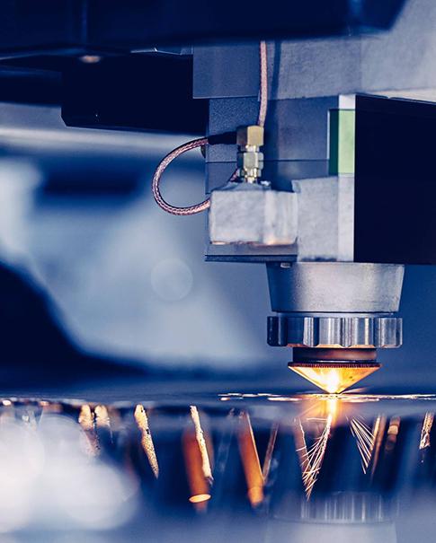
CNC lathes remain one of the most important machine types in modern manufacturing, powering industries from automotive to aerospace with accuracy, speed, and repeatability. If you're researching CNC lathing for your next project—or comparing CNC lathe machines, CNC machine lathes, or even trying to understand what is CNC lathe—this guide gives you everything you need to make informed decisions.
And if you're looking for fast, reliable machining services, we provides high-precision CNC turning and milling with instant quoting and a wide selection of materials to support both prototyping and production
Understanding CNC Lathes
Definition and Key Components of a CNC Lathe
A CNC lathe is a computer-controlled machine tool designed to rotate a workpiece while cutting tools remove material to create cylindrical or conical geometries. Unlike manual lathes, CNC lathe machines operate through programmed commands, ensuring consistent dimensions even across large production batches.
A typical CNC lathe machine includes:
Headstock: houses the spindle that rotates the part
Chuck: grips the material
Tool turret: holds multiple CNC tools
Bed & carriage: provide machine rigidity
Control system: executes CNC turning programs
Tailstock (optional): supports long workpieces
These elements work together to deliver smooth, accurate cutting, making CNC lathing suitable for both simple shafts and highly complex components.
Differences Between CNC Lathes and Conventional Lathes
Conventional lathes require manual adjustments, which slows down production and introduces human error. A CNC machine lathe, by contrast, runs automated toolpaths defined in G-code. The benefits include:
Faster cycle times
Higher precision and repeatability
Better safety
Ability to handle complex geometries
Automated multi-tool operations
For manufacturers needing accuracy within microns or consistent production day after day, CNC lathes outperform manual machines in every category.
Core Advantages of CNC Lathing
CNC lathing offers several strong advantages:
Superior roundness and concentricity for rotational parts
Excellent surface finish due to continuous cutting
Strong material compatibility, including aluminum, steel, stainless steel, copper, brass, plastics, and more
Great scalability, from prototypes to mass production
Tight tolerances, often ±0.005 mm on high-end systems
These strengths explain why CNC lathe machines remain foundational in nearly all manufacturing sectors.
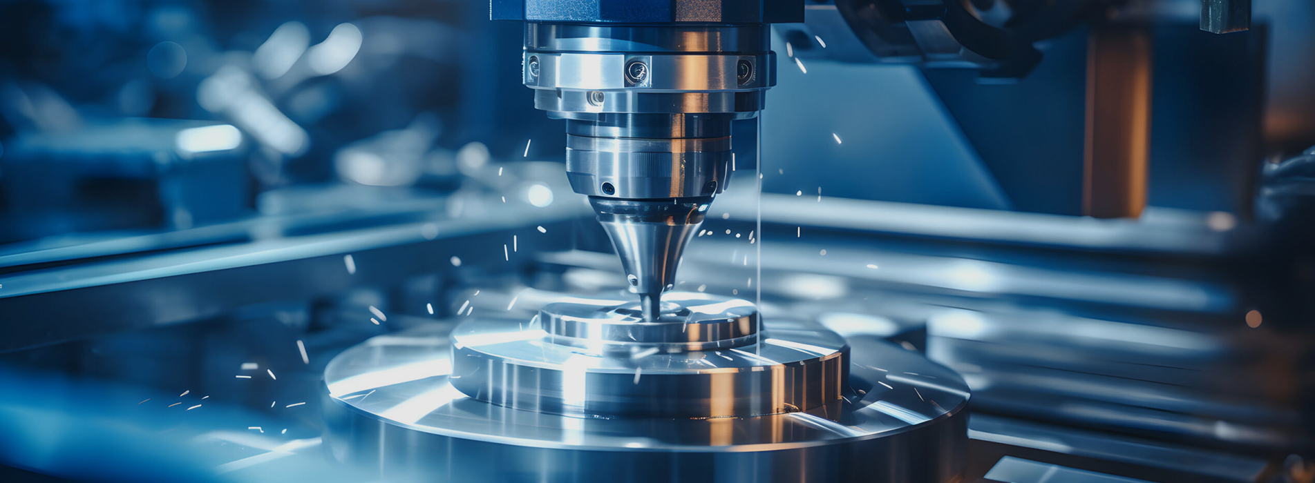
How CNC Lathe Machines Work
Overview of the Lathing Process
The CNC lathing process begins by mounting raw material—typically a bar or billet—into the chuck. As the spindle rotates the workpiece, CNC cutting tools move linearly along X and Z axes to remove material and create the desired geometry. CNC lathing is especially efficient for:
Shafts
Pins
Bushings
Sleeves
Threads
Custom cylindrical forms
Because the workpiece rotates while the tool moves, the process is optimized for parts where diameter features dominate.
CNC Programming Basics for Turning Operations
At the heart of every CNC lathe machine is a program composed of G-code and M-code. These commands tell the machine:
How fast to the spindle rotate
How quickly do cutting tools feed into the material
Which tools to activate
What path should the tool follow
Programs are often written manually for simple parts or generated with CAD/CAM software for complex geometries. Understanding these fundamentals is essential for efficient CNC lathing.
Motion Control and Spindle Operation
CNC lathes synchronize motion between the spindle and cutting tools. Toolpaths rely on precise feed rates, calculated surface speeds, and appropriate depth of cut. Advanced CNC machine lathes use:
Servo motors for precise tool motion
Variable-frequency drives to control spindle speed
Automatic tool changers for seamless multi-operation machining
Together, these systems deliver both speed and accuracy.
Common Types of CNC Lathe Machines
Horizontal CNC Lathes
Horizontal CNC lathes are the most widely used type of turning equipment, with the spindle oriented parallel to the machine bed. They excel at machining long, cylindrical parts and support both small-batch and mass production. Because chips naturally fall away from the cutting zone, these machines offer excellent chip evacuation, stable cutting conditions, and flexible turret configurations.
Sizes range from compact turning centers—ideal for small parts—to heavy-duty industrial lathes capable of handling workpieces hundreds of millimeters in diameter. Many horizontal machines can be equipped with bar feeders, automatic loading systems, and sub-spindles to improve throughput.
Key factors to evaluate include bed rigidity, spindle torque and speed, turret capacity, and the maximum turning diameter/length ratio (L/D), which influences stability and machining efficiency.
Typical applications: shafts, bearing housings, cylinders, gear blanks, and various rotational components.
Vertical CNC Lathes
Vertical CNC lathes position the spindle vertically, with the workpiece mounted on a horizontal table. This configuration is ideal for large-diameter, short-height components, as gravity assists with part positioning and workholding stability. It also makes loading heavy parts safer and easier.
Vertical lathes are known for exceptional rigidity when handling large, heavy, or wide workpieces, making them a staple in industries requiring oversized components.
Important considerations include maximum turning diameter, table load capacity, machine rigidity, and spindle power.
Typical applications: large flanges, disks, turbine housings, rotors, and components for wind power, construction, and heavy machinery.
Precision CNC Lathes and Multi-Axis Machines
Precision CNC lathes and multi-axis turning centers are designed for complex geometries and ultra-tight tolerances. These machines often include high-precision linear guides, thermal compensation systems, scale feedback, and advanced CNC controls.
Multi-axis machines may integrate C-axis, Y-axis, sub-spindles, and driven tooling, allowing complete machining—turning, milling, drilling, and tapping—in a single setup. This reduces cycle time, improves accuracy, and eliminates secondary operations.
Precision machines commonly use high-speed, low-vibration spindles and rigid tooling systems (such as HSK or BT holders) to deliver micron-level accuracy and excellent surface finishes.
Typical applications: medical implants, aerospace components, precision instrument parts, high-end mold components, and any part requiring complex profiles or tight tolerances.
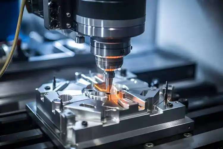
CNC Lathe vs Other CNC Machines
Key differences between CNC lathes and mills
A CNC lathe operates by rotating the workpiece at high speed while the cutting tool remains stationary or moves along a controlled axis. This turning-based process makes it exceptionally effective for producing round, tubular, and symmetrical shapes with consistent concentricity. CNC mills, on the other hand, remove material using a rotating cutting tool that moves across multiple axes. Milling machines are better suited for flat surfaces, slots, pockets, and complex 3D forms. Compared with milling, a CNC lathe generally delivers higher efficiency for rotational components, faster material removal for cylindrical profiles, and tighter geometric tolerances for features such as diameters, tapers, and threads. If you're interested in understanding milling processes in more depth, you can continue with our Bed Milling Explained.
Advantages of using a lathe for specific parts
When manufacturing shafts, bushings, pins, spacers, and threaded connectors, a CNC lathe offers superior stability and repeatability. The continuous rotation of the workpiece allows for smooth surface finishes and accurate dimensional control, especially on long or slender parts. For high-volume production, the turning process significantly reduces cycle time, lowering overall machining costs. Modern CNC lathes can also integrate operations such as drilling, tapping, grooving, and parting directly into the same setup, minimizing repositioning errors. This combined functionality is highly beneficial for parts that require multiple machining steps but must maintain tight tolerance alignment across all features.
Application scenarios
A CNC lathe is widely applied across automotive, aerospace, medical devices, consumer electronics, industrial automation, and custom hardware manufacturing. Common examples include motor shafts, gear blanks, threaded inserts, precision fasteners, hydraulic fittings, valve components, connector housings, bearing parts, and high-accuracy prototypes. It is especially valuable in scenarios where roundness, diameter precision, and concentricity are critical. In prototyping, a CNC lathe supports quick iteration with consistent dimensional results, while in mass production, it ensures stable quality with efficient material utilization and reduced machining time.
How Much Does a CNC Lathe Cost?
Factors Affecting CNC Lathe Pricing
CNC lathe machine cost varies widely. Key pricing factors include:
Machine size and rigidity
Horizontal vs vertical configuration
Precision and number of axes
Control system brand
Maximum spindle speed
Tool turret capacity
Production-grade CNC lathes typically cost more because they offer tighter tolerances and faster cycle times.
Typical Cost Ranges
Approximate global pricing:
Entry-level CNC lathes: $6,000–$15,000
Mid-range industrial machines: $20,000–$80,000
High-end multi-axis lathes: $100,000–$350,000+
Operational costs—tooling, maintenance, power—should also be considered.
Tips to Optimize Machining Cost
Choose the right machine size for your parts
Avoid unnecessary tolerances
Select easily machinable materials
Minimize tool changes
Optimize programming to reduce air-cutting time
For outsourcing, we offers instant quoting that automatically identifies cost-drivers, helping teams refine designs early.
Applications of CNC Lathes
CNC lathes play a foundational role in modern manufacturing because they can produce rotational, symmetric, and highly accurate parts at scale. Their precision, repeatability, and ability to cut complex geometries with minimal human intervention make them essential across countless industries. Whether the requirement is tight tolerances, smooth surface finishes, or efficient mass production, CNC lathing remains one of the most reliable machining processes in use today.
Industries Using CNC Lathes
CNC lathes are used in nearly every engineering sector, but several industries rely on them heavily due to the demanding tolerances and durability their components require:
Automotive & TransportationEngine components, shafts, bushings, fasteners, gearbox parts, and custom aftermarket components are frequently produced by CNC lathes. High-volume turning ensures consistent performance under thermal and mechanical stress.
Aerospace & DefensePrecision is non-negotiable in aerospace. CNC lathes produce lightweight, high-strength components such as actuator housings, turbine rings, hydraulic fittings, and threaded connectors with strict tolerance control.
Industrial Machinery & RoboticsCNC lathes create spindle components, couplings, rollers, sleeves, and automation parts that require stable roundness and wear resistance for long-term performance.
Electronics & EnergyConnectors, insulators, sensor housings, and precision terminals are often lathe-machined. In the energy sector, CNC lathes support oil & gas tools, power equipment, and high-pressure fittings.
Medical DevicesSurgical instruments, orthopedic implants, dental components, and small precision parts benefit from the lathe's ability to deliver micron-level accuracy and clean surface finishes.
Custom Manufacturing & PrototypingFor low-volume custom parts, CNC lathes provide fast turnaround, tight tolerances, and cost-effective production—ideal for R&D teams and product development.
Common Parts Produced by CNC Lathes
Because lathes specialize in rotational parts, the most frequently produced components include:
Shafts, rods, axles, and pins
Sleeves, bushings, spacers
Nuts, bolts, threaded inserts
Fittings and couplings
Housings and cylindrical enclosures
Hydraulic and pneumatic components
Bearings rings and precision rollers
These parts typically require excellent concentricity, smooth surface finish, and predictable dimensional accuracy—strengths that CNC lathes consistently deliver.
Benefits in Manufacturing
The widespread use of CNC lathes stems from several tangible advantages that make them valuable in both prototype and production environments:
Outstanding repeatability
Once programmed, CNC lathes replicate parts with minimal deviation, making them ideal for mass production.
High efficiency and speed
Automated turning dramatically shortens cycle times for cylindrical components compared with manual lathes or milling solutions.
Superior surface finishes
Lathes can achieve extremely smooth finishes—often without secondary grinding—reducing total manufacturing time.
Wide material compatibility
Metals (aluminum, steel, stainless steel, brass, copper, titanium), plastics, and composites can all be effectively machined.
Cost-effective production
For cylindrical parts, CNC lathing is often the most economical manufacturing method due to optimized toolpaths and reduced machining passes.
Whether for precision machining, high-volume production, or rapid prototyping, CNC lathes remain one of the most versatile and indispensable tools in modern manufacturing.
 SUBSCRIBE TO OUR NEWSLETTER